Experimental Demonstration of Scattering Suppression in AuNP-Coated Dielectric Microspheres
Imran Khan — A proof of concept(POC) experiment
1. Introduction & Motivation
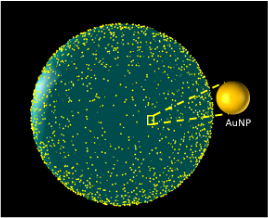
Plasmonic cloaking via nano-assembled AuNP shells has been extensively studied in modeling and simulation. This analysis is a experimental validation of these concepts through the fabrication, characterization, and optical measurement of AuNP-coated dielectric microbeads.
This analysis focuses on:
- Fabrication of 3D plasmonic metashells
- SEM analysis and surface coverage estimation
- Integrating sphere measurements to quantify scattering
suppression
- Comparison of experimental results with simulation predictions
- Discussion of discrepancies, limitations, and implications
This experimental workflow demonstrates an end-to-end proof-of-concept that the plasmonic cloaking effect predicted by simulations can be observed in physical systems.
2. Fabrication of Plasmonic Metastructures
2.1 Materials
- Silica microspheres 500nm , and 700nm
- 20 nm citrate-stabilized AuNPs
- N-[3-(Trimethoxysilyl)propyl]ethylenediamine (TMSPA) for surface
functionalization
- Ethanol, DI water
2.2 Functionalization Procedure
- Silica microspheres were cleaned in ethanol/water mixtures.
- Surface functionalization with 1% TMSPA created a
positively charged surface.
- Functionalized beads were washed to remove unbound silane compounds.
2.3 AuNP Coating
- Beads were suspended in AuNP solution.
- Electrostatic attraction enabled AuNP self-assembly
onto the functionalized surface.
- Centrifuge duration controlled filling fraction.
- Suspensions were centrifuged and rewashed to remove excess AuNPs.
A monolayer plasmonic shell was formed through this self-assembly mechanism.
3. SEM Imaging & Filling Fraction Analysis
3.1 Sample Preparation
- A drop of coated beads was placed on glass sides for optical characterization.
- Samples were dried and sputter-coated with a thin layer (when required for charging mitigation) of a silicon substrate for SEM characterization.
3.2 Characterization
UV-Vis spectroscopy:
- As-obtained AuNP from the manufacturer showed much higher absorbance compared to the TMSPA functionalized silica core.
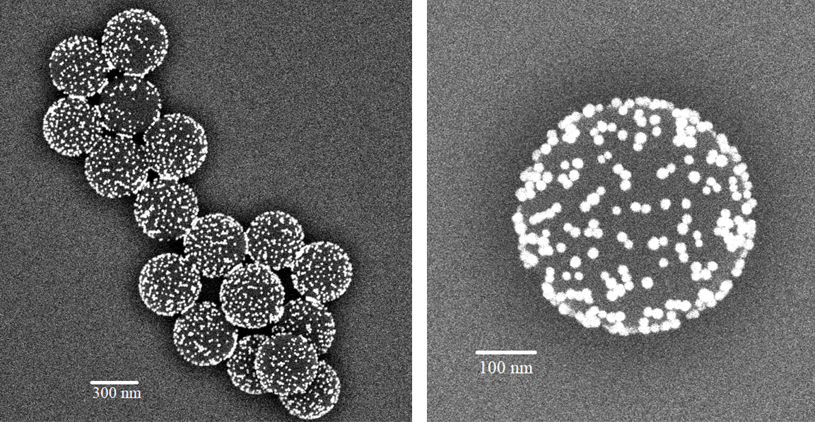
SEM was used to:
- BSD (backscatter detector) was used dominantly
- verify coating uniformity
- assess AuNP distribution
- quantify surface coverage
Images were acquired at several magnifications between 5k× and 40k×.
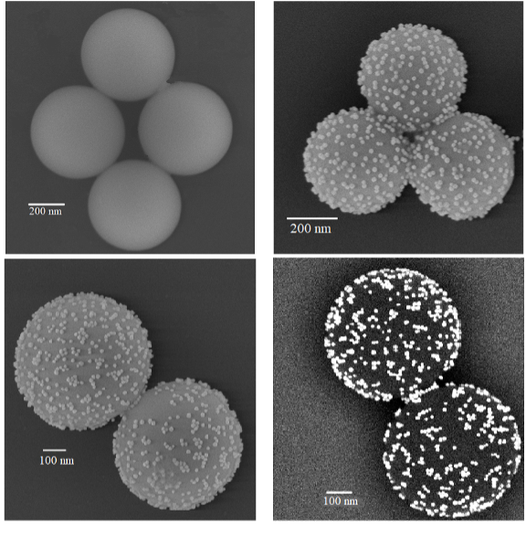
Silica spheres showed varied distribution of AuNPs on the surface.
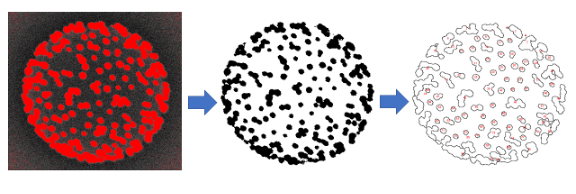
3.3 AuNP Filling Fraction Using ImageJ
- SEM image converted to grayscale.
- Thresholding applied to isolate nanoparticles.
- Particle counting performed using ImageJ’s Analyze
Particles module.
- Surface coverage percentage computed as:
\[ f = \frac{N_{\text{AuNP}} \, \pi r_{NP}^2}{4\pi a^2} \]
Typical filling fractions were 25–32%, consistent with simulation assumptions.
4. Integrating Sphere Setup for Scattering Measurement
4.1 Measurement Concept
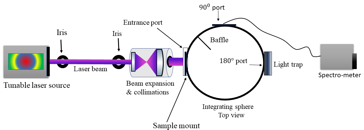
An integrating sphere spectrophotometer was used to capture the total scattering.
4.2 Optical Setup
- Tunable laser source
- Monochromator
- Integrating sphere with >97% reflectance
- Sample port designed for drop-cast bead films
4.3 Sample Preparation
- AuNP-coated and bare beads were drop-cast on glass slides
- Dried to form thin monolayers/clusters
- Ensured consistent sample morphology across runs
4.4 Calibration Process
- Baseline (bare substrate)
- Reference (BaSO₄ standard)
Ensured accurate scattering extraction independent of substrate/reflection contributions.
5. Scattering Measurement Procedure
- Mono chromatic light passed through the sample.
- Scattered light integrated by the sphere.
- Wavelength scanned from 350–800 nm.
- Measurements taken for both bare and coated beads.
- Suppression quantified as:
\[ S(\lambda) = \frac{\sigma_{\mathrm{sca,\,coated}}(\lambda)}{\sigma_{\mathrm{sca,\,bare}}(\lambda)} \]
6. Experimental Results
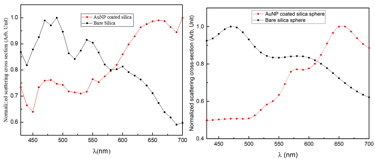
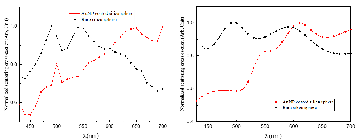
Key Findings
- Clear scattering reduction observed in
400–600 nm, corresponding to AuNP plasmon
resonance.
- Suppression magnitude: 10–20% relative to bare
beads.
- Enhancement above 650 nm consistent with simulation
predictions.
- Spectral dip matches the AuNP extinction spectrum, confirming plasmonic contributions.
7. Comparison with Simulation Predictions
| Aspect | Simulation | Experiment |
|---|---|---|
| Suppression Window | 380–600 nm | 420–560 nm |
| Dip Magnitude | 30–40% | 10–20% |
| Angular Redistribution | Strong forward bias | Weak but present |
| NP Distribution | uniform | partial clustering |
| Filling Fraction | controlled | measured 25–32% |
Agreement: Band location + physical trend.
Differences: Due to fabrication variability +
clustering + substrate effects.
8. Physical Interpretation
8.1 Multiple Scattering + Absorption
AuNPs absorb and re-radiate, damping coherent Mie oscillations.
8.2 Cluster-Induced Plasmonic Coupling
Clusters increase local plasmonic interactions → modifies extinction behavior.
8.3 Substrate Interaction
Drop-cast films couple to substrate, shifting scattering minima.
8.4 Non-Uniform Filling Fraction
Ideal monolayer assumption breaks, reducing suppression amplitude.
9. Limitations & Future Work
Limitations
- Drop-cast geometry not uniform
- SEM only captures top hemisphere
- Substrate modifies scattering behavior
- AuNP clustering not controlled
Future Improvements
- Microfluidic monolayer assembly
- Spin-coating for uniform films
- Angular-resolved dark-field scattering
- Coupled Maxwell simulations including substrate
- Machine-learning surrogate models for morphology–scattering mapping
10. Summary
This experimental investigation:
- Demonstrates scattering suppression using AuNP-coated silica
spheres
- Confirms spectral alignment with plasmonic extinction band
- Validates simulation predictions qualitatively
- Proves feasibility of plasmonic cloaking concepts in physical systems
This bridges simulation ↔︎ fabrication ↔︎ measurement, showcasing full-stack experimental and computational capability.
Acknowledgments
I would like to thank Dr.Zachary Petrek from the Chemistry Department for his valuable insight into optimizing AuNP surface functionalization and improving nanoparticle yield during the self-assembly process. His contributions were essential to the fabrication and characterization workflow used in this experimental study.
Citation (PhD Dissertation):
Khan, M. I. (2021). Tuning far-field light–matter interactions using three-dimensional plasmonic meta-structures. Ph.D. Dissertation, University of California, Merced. https://escholarship.org/uc/item/62q0s8f8