Scattering by Nanoplasmonic Mesoscale Assemblies
Imran Khan
1. Introduction & Motivation
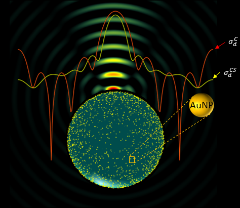
Nanoplasmonic mesoscale assemblies — dielectric microspheres coated with disordered gold nanoparticle (AuNP) shells — offer a versatile platform for tunable optical scattering, angular redistribution, and mesoscale photonic modulation.
Unlike classical Mie scattering, where a dielectric sphere produces oscillatory forward/backward lobes, the introduction of AuNPs dramatically alters the spatial distribution of scattered power. This deep dive examines how plasmonic nanoparticle coatings reshape the angular scattering profile and identifies the physical mechanisms that smooth sidelobes and enhance forward scattering.
This work is grounded in a hybrid computational framework that couples:
- Method of Fundamental Solutions (MFS) for the
dielectric core
- Foldy–Lax multiple scattering theory for the AuNP ensemble
The combined model explicitly accounts for:
- NP–NP interactions
- NP–core interactions
- far-field angular scattering
- extinction, scattering, and absorption spectra
- anisotropy and albedo
2. Physical Intuition: Why Nanoparticle Shells Reshape Angular Scattering
A bare dielectric microsphere exhibits the classical Mie like scattering pattern:
- a strong forward peak
- a secondary backward lobe
- oscillatory sidelobes due to partial-wave interference
Adding a disordered ensemble of AuNPs immediately changes this picture.
The AuNP Shell Introduces Three Key Effects
Phase decoherence
Multiple scattering inside the shell destroys the coherent interference required to sustain sidelobes.Absorption-driven damping
Metallic nanoparticles absorb a portion of incoming energy, reducing high-frequency oscillatory components.Enhanced forward scattering
Plasmonic particles radiate preferentially in forward directions, especially when near a dielectric interface.
The result:
A smoother, more forward-directed angular scattering profile.
This holds true in both scattering suppression and enhancement regimes.
3. Computational Model
We simulate the core–shell system using:
- interior field \( \Psi^{int} \)
- exterior core-scattered field \(\Psi^{core} \)
- AuNP-scattered field \( \Psi^{NP}_{n}(r) \)
- exciting fields \( \Psi^{E}_{n} \)
- incident plane wave \(\Psi^{inc} \)
3.1 MFS Representation of the Core
We start with a core(dielectric sphere) of radius $a$ at the origin of our coordinate system so that \(|r| < a \) co rresponds to its interior , \( |r| > a \) corresponds to its exterior, and \(|r|= a \) corresponds to its boundary surface. The wavenumber interion to the core is \(k_{1}\) and exterion is \(k_{0}\). We use the method of fundamental of solutions (MFS) to compute \(\Psi^{int}\) \(\Psi^{core}\). To do so, let \(\hat{s}_{m}\) for \(m = 1,...,M\) denotes \(M\) points that sample the uting sphere so \(|\hat{s}_{m}| = 1\) for \(m=1,...,M\). We introduce a length \(\mathcal{l} << a\) and express ,
Interior field:
\[ \Psi^{int}(r) \approx \sum_{m=1}^{M} \frac{e^{ik_{1}|r-(a+\mathcal{l})\hat{s}_{m}| }} {4\pi |r-(a+\mathcal{l})\hat{s}_{m}|}c_{m}, |r|< a \]Hence, the evaluation of the above equation is an \(\textit{exact}\) solution of
\[ \left(\nabla^{1} + k_{1}^{2}\right) \Psi^{int} = 0 \]Similarly, exterior field:
\[ \Psi^{core}(r) \approx \sum_{m=1}^{M} \frac{e^{ik_{0}|r-(a-\mathcal{l})\hat{s}_{m}|} }{4 \pi |r-(a-\mathcal{l})\hat{s}_{m}|}b_{m}, |r| > a. \]Thsi superposition of Green's function \(\textit{exactly}\) satisfies
\[\left( \nabla^{2} + k_{0}^{2}\right) \Psi^{int} = 0 , |r| > a \]Moreover , each Greens function satisfies the correct radiation condition for \(|r|\to\infty \), so the equation above the last ensures that \(\Psi^{core}\) is appropriately outgoing.
Where:
- \(\pm \mathcal{l}\) offsets keep sources outside their respective regions
- Fibonacci sphere sampling ensures uniform collocation
3.2 AuNP Scattering Model
Each AuNP is treated as an isotropic point-scatterer:
\[\Psi_{n}^{NP}(r) = \alpha_{n} \frac{e^{ik_{0}|r-r_{n}|}}{4\pi |r-r_{n}|} \Psi^{E}_{n}, n = 1,...,N, \]With \(r_{n}\) is the center position of \(\textit{nth}\) gold nanoparticles, \(\alpha_{n} \) denoting its scattering amplitide, and \(\Psi^{E}_{n}\) as the exciting field.
Scattering amplitude: \[ \alpha = \left[\frac{\sigma_{s}}{4\pi} - \left(\frac{k_{0}\sigma_{t}}{4\pi} \right)^{2} \right]^{1/2} + i\frac{k\sigma_{t}}{4\pi} \]
Here \(\sigma_{s}\) and \(\sigma_{t} \) denote the scattering and total cross-sections of the individual AuNP
This embeds:
- scattering
- absorption
- radiation damping
- optical theorem constraints
3.3 Foldy–Lax Multiple Scattering
Exciting field at NP (n):
\[ \Psi_{n}^{E} = \sum_{m=1}^{M} G_{0}(|r_{n}-(a-\mathcal{l})\hat{s}_{m}|)b_{m} + \sum_{\substack{ n^{'}=1 \\ n^{'} \neq n} }^{N} \alpha_{n^{'}} G_{0}(|r_{n}-r_{n^{'}}|)\Psi_{n'}^{E}, n = 1,...,N \]Here \(G_{0}(R)=e^{ik_{0}R} / (4\pi R)\). This yields a fully dense (N N) system.
3.4 Boundary Conditions → Block Linear System
Boundary continuity:
The field scattered by the nanoplasmonic mesoscale assembly is:
\[\Psi^{sca} = \Psi^{core} + \sum_{n=1}^{N}\Psi_{n}^{NP} \]
We relate \(\Psi^{sca}\) with \( \Psi^{int}\) and the incident filed \(\Psi^{inc}\) in the following way:
\[ \Psi^{inc} + \Psi^{sca} = \Psi^{int} \] and
\[ \partial_{n}\Psi^{inc} + \partial_{n}\Psi^{sca} = \partial_{n}\Psi^{int} on |r| = a \]
Resulting in the coupled system:
[ A1  A2  B1 ] [ b ] = [ f ]
[ A3  A4  B2 ] [ c ]   [ g ]
[      C    D ] [ψE]   [ 0 ]
Matrix size: (2M + N) × (2M + N).
4. Scattering Cross-Sections and Angular Metrics
4.1 Far-Field Amplitude
\[ f(\hat{o},\hat{\mathcal{i}}) = \frac{1}{4\pi} \sum_{m=1}^{M}e^{-ik_{0}(a-\mathcal{l})\hat{o}\cdot\hat{s}_{m}}b_{m}(\mathcal{i}) + \frac{1}{4\pi} \sum_{n=1}^{N}\alpha_{n}e^{-ik_{0}\hat{o}\cdot r_{n} }\Psi_{n}^{E}(\mathcal{i}) \]
4.2 Differential Cross-Section
\[ \sigma_{d}(\hat{o}, \hat{\mathcal{i}}) = |f(\hat{o},\hat{\mathcal{i}})|^{2} \]
4.3 Total Cross-Section (Optical Theorem)
\[ \sigma_{t} = \frac{4\pi}{k_{0}} Im \{f(\hat{\mathcal{i}},\hat{\mathcal{i}})\} \] , and \[ \sigma_{s} = \int_{4\pi} \sigma_{d}(\hat{o},\hat{\mathcal{i}})d\hat{o} \]
4.4 Scattering Albedo
\[ \bar{\omega}_{0} = \sigma_{s} / \sigma_{t}\]
4.5 Anisotropy Factor
\[ g = \frac{1}{\sigma_{t}}\int_{4\pi}(\hat{o}.\hat{\mathcal{i}})\sigma_{d}(\hat{o},\hat{\mathcal{i}})d\hat{o} \] The anisotropy factor(\(g\)) gives a measure of the amount of power flow in forward/backward directions. When \(g = 0\), scattering is isotropic, and when \(g = \pm 1\), scattering is purely in the forward or backward directions, respectively.
5. Results & Interpretation
5.1 Scattering Efficiency
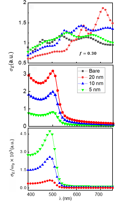
Findings:
- Bare core shows strong Mie like scattering peaks
- 20 nm NPs suppress resonances 400–600 nm
- 5 nm NPs exhibit weak spectral influence
5.2 Core-Size Dependent Suppression/Enhancement
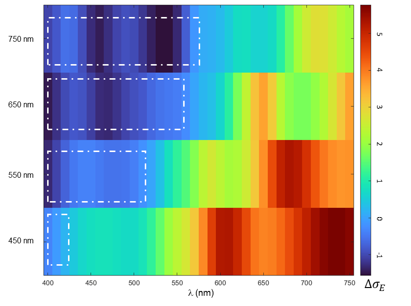
- 750 nm → broad suppression window
- 450 nm → narrow suppression, large enhancement
5.3 Differential Cross-Section: Angular Redistribution
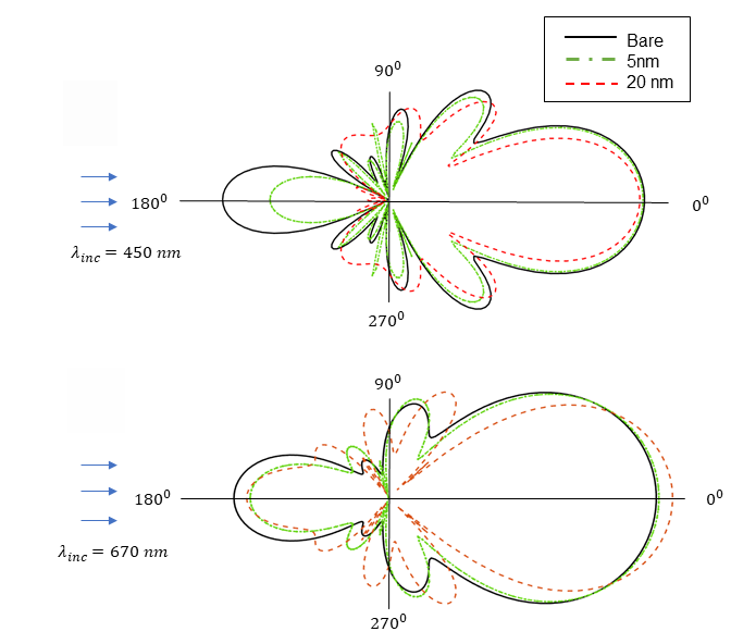
Key takeaways:
- Backward lobe strongly reduced with 20 nm NP shell
- Forward lobe sharpened and intensified
- Angular sidelobes smoothed
This confirms phase decoherence + multiple scattering.
5.4 Henyey–Greenstein (HG) Fit
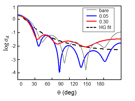
HG model: \[\sigma_{d}^{HG} = \frac{\sigma_{s}}{4\pi} \frac{1-g^{2}}{(1+g^{2}-2g\cos\theta)^{3/2}} \]
Plasmonic coated spheres match HG extremely well.
5.5 Anisotropy
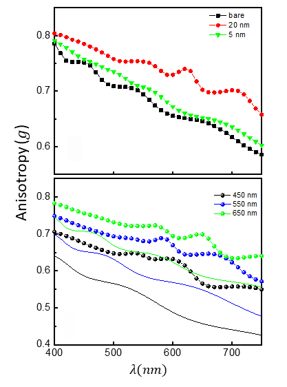
- 20 nm AuNP shells → highest g
- Forward scattering consistently enhanced
- Holds across all core sizes
6. Mechanisms Behind Angular Smoothing
6.1 Multiple-Scattering Induced Decoherence
Random AuNP distribution breaks phase alignment.
6.2 Absorption Dampens Oscillatory Features
Intrinsic AuNP absorption reduces partial-wave interference.
6.3 Forward Bias from Plasmonic Radiation
AuNPs radiate strongly forward at visible wavelengths.
7. Limitations & Future Work
Limitations
- scalar wave model
- no near-field coupling between NPs
- O(N³) solver scaling
- isotropic NP scattering assumption
Future Enhancements
- full-vector Maxwell solvers
- FMM acceleration
- GPU-based iterative solvers
- physics-informed neural surrogates
8. Applications
- metasurface beam shaping
- near-field imaging
- forward-scattering enhancement
- radiative transfer modeling
- bio-photonic sensing
- passive cloaking
9. Summary
This full technical deep dive demonstrates that:
- AuNP shells dramatically reshape angular scattering
- forward scattering is universally enhanced
- absorption and multiple scattering suppress sidelobes
- anisotropy increases across all core sizes
- plasmonic shells can modulate both spectral and angular behavior
These findings establish nano-assembled plasmonic shells as a robust platform for mesoscale optical modulation.